Chapter 8: Serial Communication
Table of Contents
| Link | Purpose |
|---|---|
| 8. Chapter Serial Communication | Freenove’s official C version |
| Chapter 8 Serial Communication - Starter Kit for Pico | Freenove’s official video description |
| Alire crate | Alire crate containing the Ada code in this chapter |
| GNATdoc documentation for this chapter | Automatically generated HTML documentation for the Ada code in this chapter |
Serial Communication for Debugging #
There are three different ways of text-based serial communication that work well for debugging on the Raspberry Pi Pico. Each has its own advantages and disadvantages. Let me walk you through them.
Using SWD (Serial Wire Debug) and Semihosting #
This is the method that Ada.Text_IO uses by default. On the software side it is very comfortable — I simply use
Ada.Text_IO to write output and need no explicit initialisation in my own code. On the hardware and receiving side,
however, a bit more effort is required.
Hardware-wise you need an SWD compatible debug probe. For the Raspberry Pi Pico the Raspberry Pi Debug Probe is the best and cheapest option.
On the receiver side you need GDB (GNU Debugger) and OpenOCD (Open On-Chip Debugger) to connect to the debug interface. See my Side Quest: Debugger. You also need to activate semihosting.
For example, when I use Visual Studio Code I add the following to my launch configuration:
{
  "version": "0.2.0",
  "configurations": [
    {
      ...
      "openOCDLaunchCommands": [
        "adapter speed 5000",
        "init",
        "arm semihosting enable"
      ],
      ...
    }
  ]
}
The output then appears in the debugger terminal window inside Visual Studio Code.
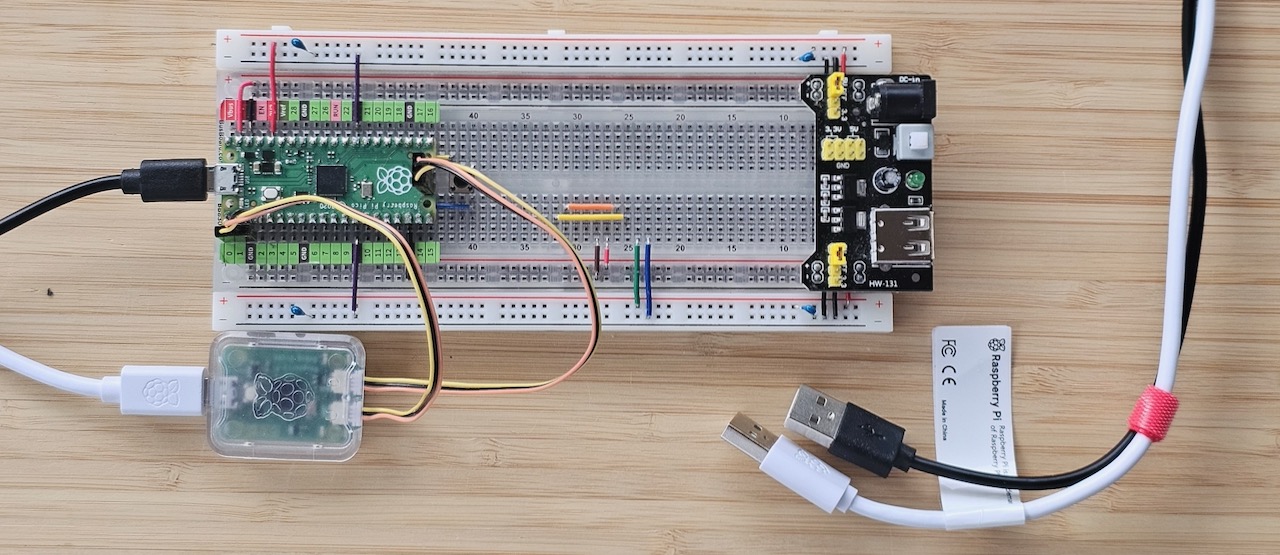
Advantages:
- Used directly by the Ada runtime
- No software initialisation needed in the program
Disadvantages:
- Only works while the debugger and Debug Probe are connected
- Very slow transfer speed which can slow down your program
- Only single-character input is available (
Get)
Using UART (Universal Asynchronous Receiver-Transmitter) #
The UART connection uses two GPIO pins to generate an RS-232 compatible signal, but at a modest 3.3 V level.
Because most traditional RS-232 devices expect voltages between ±5 V and ±15 V, the 0 V / 3.3 V output is incompatible with them. You will therefore need at least a level shifter. In most cases you will also need an RS-232 to USB cable, as modern computers no longer have a built-in RS-232 interface. I actually use a self-made solution with two level shifters because I only have an RS-232 to TTL converter available.
Fortunately the Raspberry Pi Debug Probe provides RS-232 to USB conversion and works directly with 0 / 3.3 V logic. Since I already need the Debug Probe for SWD debugging, there is no extra cost. This is the solution I use most often because it is easier to wire up and takes up less space on the breadboard.
The UARTs are not initialised by default, and the procedures RP.UART.Transmit and RP.UART.Receive are rather
low-level and cumbersome to use. Because of this I created the package Pico.UART_IO. Even so, it is still not as
comfortable to use as Ada.Text_IO.
For viewing the output you will need a serial terminal program such as CoolTerm.
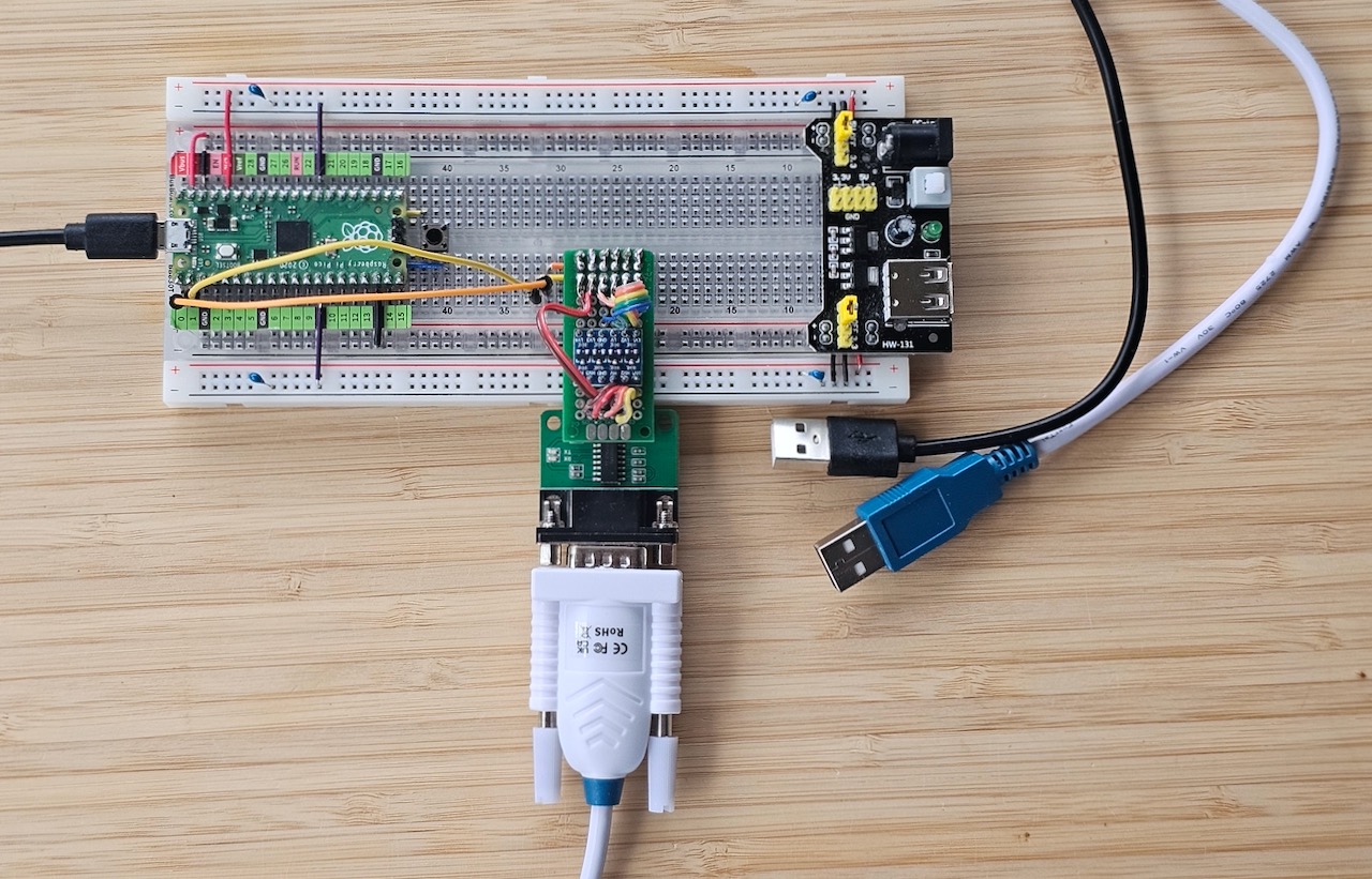
Advantages:
- Can be used without a Debug Probe (if you already have a level shifter / USB-to-TTL adapter)
- Output in a dedicated terminal window is usually easier to read than inside an IDE
Disadvantages:
- Uses two GPIO pins and one of the two available UART peripherals
- Requires more complex setup and additional hardware
Using USB CDC-ACM (Communications Device Class - Abstract Control Model) #
Trust the USB consortium to come up with a strange name. CDC-ACM allows an RS-232 compatible serial connection over USB, complete with flow control. The presence of flow control is important when configuring your terminal program.
Hardware-wise nothing more than a USB cable is needed.
Software-wise it is the most complex option to set up. I had to start the USB stack with a handler for serial
communication and set up an interrupt handler. Once everything is running, USB.Device.Serial.Write (and the
corresponding read function) are even more cumbersome to use than the UART equivalents. Both directions use a small ring
buffer to hold the I/O data. Unlike normal ring buffers, however, they do not block when full or empty — they simply
return immediately with zero bytes processed.
I also had to check USB.Device.Serial.List_Ctrl_State.DTE_Is_Present before every operation to ensure a Data Terminal
Equipment was actually connected at the other end.
In the end I wrote a retry mechanism so that I could read and write without worrying whether the data would actually
arrive. The library retries the send and receive operations and executes a delay until after each unsuccessful
attempt. It continues retrying until the timeout period has elapsed and only then gives up. Of course, it returns
immediately after a successful operation. The only exception is Read_Line, which I left blocking.
For this chapter I am using my Pico.USB_IO implementation, which solves all these problems and keeps the sample code
readable.
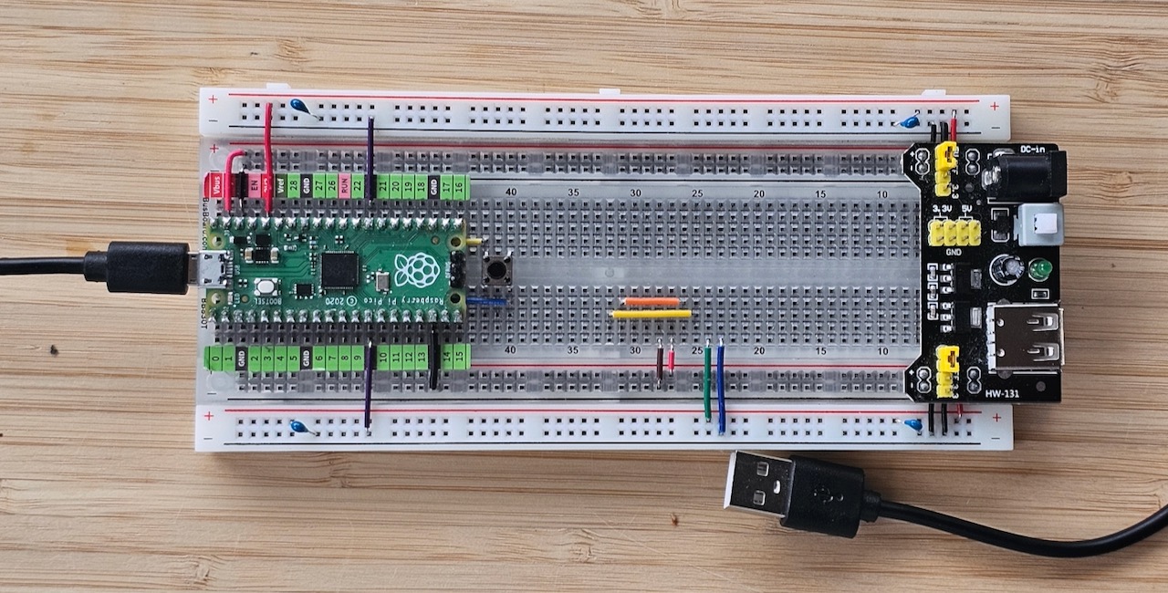
Advantages:
- Needs no special hardware beyond a USB cable
- You can set up to seven CDC-ACM connections simultaneously
- Output in a dedicated terminal window is usually easier to read than inside an IDE
Disadvantages:
- Uses two IN endpoints and one OUT endpoint out of the total 2×16 available
- Requires complex initialisation, especially when multiple USB devices are used
- Read and write operations need complex retries as only 64-byte blocks are transferred
- Read operations can lose data when more than approximately 128 bytes are transferred at once
Project Serial Print #
With all the complex logic hidden away inside the pico_xbsp crate, the actual serial communication is just as simple as in the original Freenove example.
This program demonstrates all three output methods at once — USB, UART and SWD (Serial Wire Debug). It prints the same message to three different consoles. You will need to open three separate terminals (or one terminal plus the debugger) to see all the output. The USB and UART messages appear in ordinary terminal programs, while the SWD output appears in the debugger console.
In real applications I strongly recommend using only one output method. Running all three at the same time produces
a lot of duplicate output and can affect performance. Alternatively you can use my Pico.Debug_IO package, which can be
configured via Alire build settings to select the desired output channel.
Note that Pico.UART_IO and Pico.USB_IO must be initialised manually, whereas Ada.Text_IO is initialised
automatically by the semihosting framework.
procedure Sketch_08_1_Serial_Print with
   No_Return
is
   package RT renames Ada.Real_Time;
begin
   Pico.USB_IO.Initialise;
   Pico.UART_IO.Initialise;

   Pico.USB_IO.Put_Line ("USB: Raspberry Pi Pico initialization completed!");
   Pico.UART_IO.Put_Line ("UART: Raspberry Pi Pico initialization completed!");
   Ada.Text_IO.Put_Line ("SWD: Raspberry Pi Pico initialization completed!");

   loop
      Pico.USB_IO.Put_Line ("USB: Clock = " & RT.Clock'Image);
      Pico.UART_IO.Put_Line ("UART: Clock = " & RT.Clock'Image);
      Ada.Text_IO.Put_Line ("SWD: Clock = " & RT.Clock'Image);

      delay 1.0;
   end loop;
exception
   when E : others =>
      Ada.Text_IO.Put_Line ("=== UNHANDLED EXCEPTION ===");
      Ada.Text_IO.Put_Line ("! " & Ada.Exceptions.Exception_Name (E));
      Ada.Text_IO.Put_Line ("! " & Ada.Exceptions.Exception_Message (E));
      raise;
end Sketch_08_1_Serial_Print;
Project Serial Read and Write #
This example shows how to read from and write to all three serial ports. Note that standard Ada.Text_IO only provides
a Get procedure for single characters. The AdaCL_Embedded library
contains a package called AdaCL.Text_IO with the missing Get_Line and similar functions, but I have not used it in
this example.
I initialise the USB and UART interfaces with increased read timeouts to allow comfortable user input. Pico.USB_IO
also requires a retry rate. For this example I have set 10,000 retries over 60 seconds (roughly one retry every 6 ms).
This gives very smooth interactive input, but is too coarse for high-speed bulk transfers.
procedure Sketch_08_2_Serial_RW with
   No_Return
is
   Text : String (1 .. 128);
   Last : Natural;
begin
   Pico.USB_IO.Set_Read_Timeout (60.0, 10_000);
   Pico.USB_IO.Initialise;

   Pico.UART_IO.Set_Read_Timeout (60.0);
   Pico.UART_IO.Initialise;

   Pico.USB_IO.Put_Line ("Please input some characters,");
   Pico.USB_IO.Put_Line ("select ""Newline"" below and click send button.");

   Pico.UART_IO.Put_Line ("Please input some characters,");
   Pico.UART_IO.Put_Line ("select ""Newline"" below and click send button.");

   loop
      Pico.USB_IO.Put ("Read line > ");
      Pico.USB_IO.Read_Line (Text, Last);
      Pico.USB_IO.Put_Line ("Text Read : " & Text (1 .. Last));

      Pico.UART_IO.Put ("Read line > ");
      Pico.UART_IO.Read_Line (Text, Last);
      Pico.UART_IO.Put_Line ("Text Read : " & Text (1 .. Last));

      Ada.Text_IO.Put ("Get character > ");
      Ada.Text_IO.Get (Text (1));
      Ada.Text_IO.Put_Line ("Text Read : " & Text (1));
   end loop;
exception
   when E : others =>
      Ada.Text_IO.Put_Line ("=== UNHANDLED EXCEPTION ===");
      Ada.Text_IO.Put_Line ("! " & Ada.Exceptions.Exception_Name (E));
      Ada.Text_IO.Put_Line ("! " & Ada.Exceptions.Exception_Message (E));
      raise;
end Sketch_08_2_Serial_RW;
Extended Board Support Package #
If you want to explore how everything works under the hood, I recommend fetching the source of the pico_xbsp crate. It includes three embedded test crates with extended tests, including bulk I/O examples.
The most interesting files and directories are:
pico_xbsp/
├── src/
│   ├── pico-uart_io.ads        # UART specification
│   ├── pico-usb_io.ads         # USB specification
│   ├── no_tasking/
│   │   ├── pico-uart_io.adb    # UART implementation (light runtime)
│   │   └── pico-usb_io.adb     # USB implementation (light runtime)
│   └── tasking/
│       ├── pico-uart_io.adb    # UART implementation (light tasking & embedded runtime)
│       └── pico-usb_io.adb     # USB implementation (light tasking & embedded runtime)
├── test_e/                     # embedded runtime tests
├── test_l/                     # light runtime tests
└── test_lt/                    # light tasking runtime tests